Good summary of events with links: https://anderegg.ca/2024/10/13/acf-has-been-hijacked
- Guideline invoked: https://github.com/wordpress/wporg-plugin-guidelines/blob/trunk/guideline-18.md
- https://x.com/wp_acf/status/1841843084700598355
| Date | Notes | Links |
|---|---|---|
| Aug. 28 | ACF 6.3.6 released |
link |
| Oct. 2/3 | ACF 6.3.7 released. Changelog: Security - ACF Free now uses its own update mechanism from WP Engine servers |
link |
| Oct. 7 | ACF 6.3.8. Changelog: Security - ACF defined Post Type and Taxonomy metabox callbacks no longer have access to $_POST data. (Thanks to the Automattic Security Team for the disclosure) |
link |
| Oct. 12 17:47 | ACF becomes SCF | Zip file metadata |
| Oct. 12 18:26 | Wordpress announcement of taking over acf: blog post |

Downloaded version 6.3.6 of advanced custom fields from github: [AdvancedCustomFields/acf](https://github.com/AdvancedCustomFields/acf/releases/tag/6.3.6)
Downloaded version 6.3.6.2 of secure custom fields from wordpress: https://wordpress.org/plugins/advanced-custom-fields/
> find . -name '*.zip'  -exec sha256sum {} \;
1403316f569fdb8947dbb0ef6f6f0f154678fe978e46ccc06571d71918c685dd  ./advanced-custom-fields.6.3.6.2.zip
91cd88e29e1c220603e17fdfc267943a16e297a87d24325eafc15794364a0a83  ./advanced-custom-fields-6.3.6.zip
Complete txt diff File list txt diff
List of changed files between the two plugins
The metadata for the Advanced Custom Fields plugin has been updated along with the package
diff -qr ./advanced-custom-fields-6.3.6/ ./advanced-custom-fields-6.3.6.2/
Files ./advanced-custom-fields-6.3.6/acf.php and ./advanced-custom-fields-6.3.6.2/acf.php differ
Files ./advanced-custom-fields-6.3.6/includes/acf-bidirectional-functions.php and ./advanced-custom-fields-6.3.6.2/includes/acf-bidirectional-functions.php differ
Files ./advanced-custom-fields-6.3.6/includes/acf-helper-functions.php and ./advanced-custom-fields-6.3.6.2/includes/acf-helper-functions.php differ
Files ./advanced-custom-fields-6.3.6/includes/acf-value-functions.php and ./advanced-custom-fields-6.3.6.2/includes/acf-value-functions.php differ
Files ./advanced-custom-fields-6.3.6/includes/admin/admin-internal-post-type-list.php and ./advanced-custom-fields-6.3.6.2/includes/admin/admin-internal-post-type-list.php differ
Files ./advanced-custom-fields-6.3.6/includes/admin/admin.php and ./advanced-custom-fields-6.3.6.2/includes/admin/admin.php differ
Files ./advanced-custom-fields-6.3.6/includes/admin/post-types/admin-field-group.php and ./advanced-custom-fields-6.3.6.2/includes/admin/post-types/admin-field-group.php differ
Files ./advanced-custom-fields-6.3.6/includes/admin/views/acf-field-group/field.php and ./advanced-custom-fields-6.3.6.2/includes/admin/views/acf-field-group/field.php differ
Files ./advanced-custom-fields-6.3.6/includes/admin/views/global/header.php and ./advanced-custom-fields-6.3.6.2/includes/admin/views/global/header.php differ
Files ./advanced-custom-fields-6.3.6/includes/admin/views/global/navigation.php and ./advanced-custom-fields-6.3.6.2/includes/admin/views/global/navigation.php differ
Files ./advanced-custom-fields-6.3.6/includes/admin/views/tools/tools.php and ./advanced-custom-fields-6.3.6.2/includes/admin/views/tools/tools.php differ
Files ./advanced-custom-fields-6.3.6/includes/assets.php and ./advanced-custom-fields-6.3.6.2/includes/assets.php differ
Files ./advanced-custom-fields-6.3.6/includes/class-acf-site-health.php and ./advanced-custom-fields-6.3.6.2/includes/class-acf-site-health.php differ
Files ./advanced-custom-fields-6.3.6/includes/fields.php and ./advanced-custom-fields-6.3.6.2/includes/fields.php differ
Files ./advanced-custom-fields-6.3.6/includes/post-types/class-acf-post-type.php and ./advanced-custom-fields-6.3.6.2/includes/post-types/class-acf-post-type.php differ
Files ./advanced-custom-fields-6.3.6/includes/post-types/class-acf-taxonomy.php and ./advanced-custom-fields-6.3.6.2/includes/post-types/class-acf-taxonomy.php differ
Files ./advanced-custom-fields-6.3.6/README.md and ./advanced-custom-fields-6.3.6.2/README.md differ
Files ./advanced-custom-fields-6.3.6/readme.txt and ./advanced-custom-fields-6.3.6.2/readme.txt differ
Plugin Manifest changes
diff --color -u --suppress-common-lines -b -r ./advanced-custom-fields-6.3.6/acf.php ./advanced-custom-fields-6.3.6.2/acf.php
--- ./advanced-custom-fields-6.3.6/acf.php	2024-08-28 07:35:13.000000000 -0700
+++ ./advanced-custom-fields-6.3.6.2/acf.php	2024-10-12 17:25:59.560336291 -0700
@@ -1,17 +1,13 @@
 <?php
 /**
- * Advanced Custom Fields
+ * Secure Custom Fields
  *
- * @package       ACF
- * @author        WP Engine
- *
- * @wordpress-plugin
- * Plugin Name:       Advanced Custom Fields
- * Plugin URI:        https://www.advancedcustomfields.com
- * Description:       Customize WordPress with powerful, professional and intuitive fields.
- * Version:           6.3.6
- * Author:            WP Engine
- * Author URI:        https://wpengine.com/?utm_source=wordpress.org&utm_medium=referral&utm_campaign=plugin_directory&utm_content=advanced_custom_fields
+ * Plugin Name:       Secure Custom Fields
+ * Plugin URI:        http://wordpress.org/plugins/advanced-custom-fields/
+ * Description:       Secure Custom Fields is a fork of the Advanced Custom Fields plugin, which will be maintained by WordPress.org, for security and functionality updates.
+ * Version:           6.3.6.2
+ * Author:            WordPress.org
+ * Author URI:        https://wordpress.org/
  * Text Domain:       acf
  * Domain Path:       /lang
  * Requires PHP:      7.4
Notes about changes
- Renames plugin fields but not the zip file
- Still points to https://wordpress.org/plugins/advanced-custom-fields/ , https://wordpress.org/plugins/secure-custom-fields/ doesn’t exist
- pointed support to https://wordpress.org/support/plugin/advanced-custom-fields/
- disables+removes acf pro functions
- removes references to documentation, and help tab
- added code from
6.3.8:Ensure the metabox being called does not perform any unsafe operations - adjust readme:
- ACF -> SCF
-ACF helps customize WordPress with powerful, professional and intuitive fields. Proudly powering over 2 million sites, WordPress developers love ACF.
+Secure Custom Fields is a free fork of the Advanced Custom Fields plugin created originally for security updates, but now includes functionality improvements to make this plugin non-commercial in the plugin directory. If you'd like to get involved, submit some code! We want the 2M+ sites that will receive this update to have the best code and functionality possible.
Changelog Replacements
+= 6.3.6.2 =
+*Release Date 12th October 2024*
+* Security - Harden fix in 6.3.6.1 to cover $_REQUEST as well.
+* Fork - Change name of plugin to Secure Custom Fields.

-[View the full changelog](https://www.advancedcustomfields.com/changelog/)
+= 6.3.6.1 =
+*Release Date 7th October 2024*

-== Upgrade Notice ==
\ No newline at end of file
+* Security - ACF defined Post Type and Taxonomy metabox callbacks no longer have access to $_POST data. (Thanks to the Automattic Security Team for the disclosure)
Latest [Relevant] Release notes
Release notes for 6.3.8, from https://github.com/AdvancedCustomFields/acf/blob/6.3.8/readme.txt :
<code>
== Changelog ==

= 6.3.8 =
*Release Date 7th October 2024*

* Security - ACF defined Post Type and Taxonomy metabox callbacks no longer have access to $_POST data. (Thanks to the Automattic Security Team for the disclosure)

= 6.3.7 =
*Release Date 2nd October 2024*

* Security - ACF Free now uses its own update mechanism from WP Engine servers

= 6.3.6 =
*Release Date 28th August 2024*

* Security - Newly added fields now have to be explicitly set to allow access in the content editor (when using the ACF shortcode or Block Bindings) to increase the security around field permissions. [See the release notes for more details](https://www.advancedcustomfields.com/blog/acf-6-3-6/#field-value-access-editor)
* Security Fix - Field labels are now correctly escaped when rendered in the Field Group editor, to prevent a potential XSS issue. Thanks to Ryo Sotoyama of Mitsui Bussan Secure Directions, Inc. for the responsible disclosure
* Fix - Validation and Block AJAX requests nonces will no longer be overridden by third party plugins
* Fix - Detection of third party select2 libraries will now default to v4 rather than v3
* Fix - Block previews will now display an error if the render template PHP file is not found
The security fix in question is related to how advanced-custom-fields processes GET and POST requests.
Files:
includes/post-types/class-acf-post-type.php/includes/post-types/class-acf-taxonomy.php
The first fix, clearing POST parameters, was added as part of acf 6.3.8
Wordpress’s fork took that fix and added clearing the GET parameters as part of it’s first release 6.3.6.2.
This didn’t incorporate the switch to pointing to
. despite the changelog referenceing POST data it looks like the change was securing GET requests.
Since it uses code from 6.3.8, it must have been available before the “fork” took place.
Instead sort of minor update? 6.3.6 -> 6.3.6.2.
Comparing fix to referenced `6.3.8` from acf
> \diff -u --suppress-common-lines -b ./class-acf-post-type-6.3.8.php ./advanced-custom-fields-6.3.6.2/includes/post-types/class-acf-post-type.php
--- ./class-acf-post-type-6.3.8.php     2024-10-12 19:26:56.058355194 -0700
+++ ./advanced-custom-fields-6.3.6.2/includes/post-types/class-acf-post-type.php        2024-10-12 17:25:59.704335853 -0700
@@ -649,12 +649,15 @@
                        }

                        $original_post = $_POST; //phpcs:ignore -- Only used as temporary storage to prevent CSRFs in callbacks.
+                       $original_request = $_REQUEST;
                        $_POST         = array();
+                       $_REQUEST         = array();
                        $return        = false;
                        if ( is_callable( $original_cb ) ) {
                                $return = call_user_func( $original_cb, $post );
                        }
                        $_POST = $original_post;
+                       $_REQUEST = $original_request;
                        return $return;
                }
The fix added is also clearing the GET parameters from the original request before calling the meta box callback function specified.
Before calling the function, it grabs it from
$original_cb  = isset( $acf_taxonomy['meta_box_cb'] ) ? $acf_taxonomy['meta_box_cb'] : false;

// Prevent access to any wp_ prefixed functions in a callback.
if ( apply_filters( 'acf/taxonomy/prevent_access_to_wp_functions_in_meta_box_cb', true ) && substr( strtolower( $original_cb ), 0, 3 ) === 'wp_' ) {
  // Don't execute register meta box callbacks if an internal wp function by default.
  return;
}
Stops attacker from being able to pass extra GET parameters to meta box callback functions when setting it for a post. To be able to call this a user must be able to register acf-taxonomy custom post types within WordPress.
// WordPress defaults to the tags/categories metabox, but a custom callback or `false` is also supported.
			$meta_box = isset( $post['meta_box'] ) ? (string) $post['meta_box'] : 'default';
Internally, acf is still used in most places.


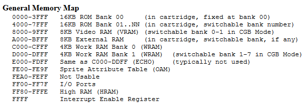
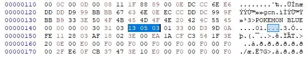
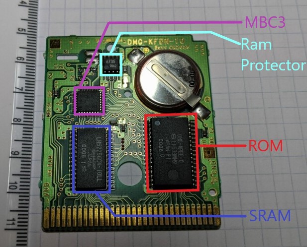
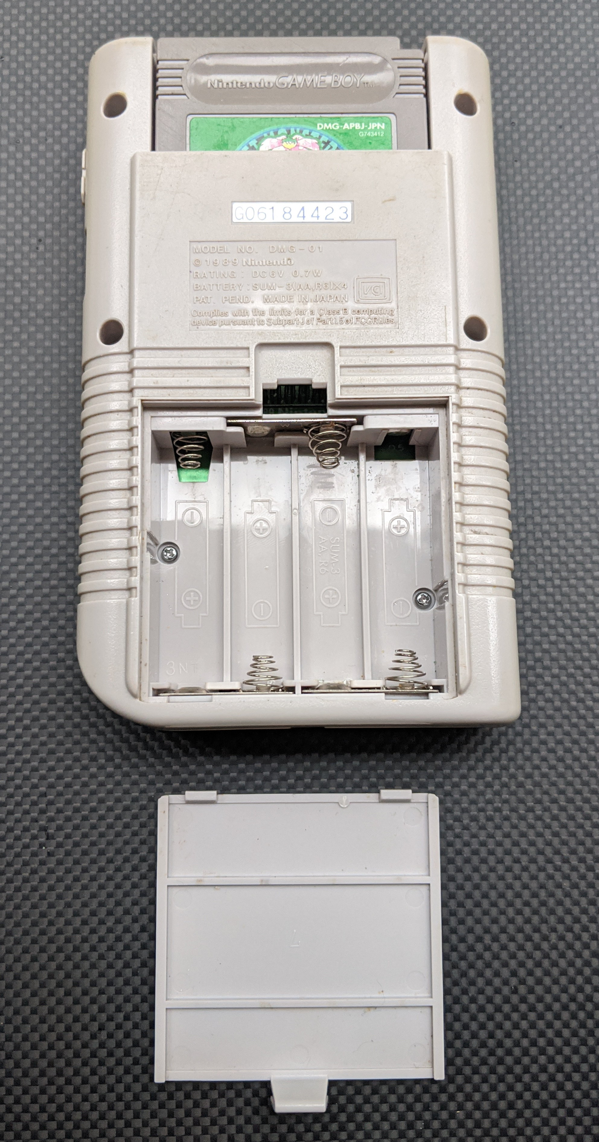
 The Gameboy DMG


